Leader line in engineering drawing Nail artwork conjures up Every person. Grades of drawing pencils are organized in a scale based on softness or hardness.

What Are Lines Types Of Lines In Engineering Drawing Youtube
Thick and visible line.
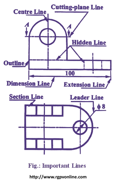
. Where a leader line is used to point towards the feature being dimensioned. Leader line Dash thick line Hidden line Chain thin line Center line. An Engineering drawing should contain the details regarding the sizes besides giving the shape of an object.
Working drawings are the set of technical drawings used during the manufacturing phase of a product. Both 1 Intensity of blackness and 2 Hardness. A harder pencil should be used such as a 2H pencil.
Draw a leader line in your web page. An engineering or technical drawing is a graphical representation of a part assembly system or structure and it can be produced using freehand mechanical tools or computer methods. New LeaderLine documentgetElementByIdstart documentgetElementByIdend.
Also Can i add Positional Tolerance without any datum like mentioned in the diagram. Line conventions in engineering drawing. Thin line with arrow or dot.
The proportion once selected should be maintained throughout the drawing. A leader line is a line referring to some form of feature that could be a dimension an object or an outline. Visible lines represent features that can be seen in the current view.
Hi I am new to Engg Drawing and confused if I can Mark Dimension with Center Lines in Engineering Drawings like the attached file. Leader line is drawn may be 30 or 60 to the bottom of dimensions. 14To draw the leader line which type of the following line is used.
They are shown in geometrical drawings only. A parallel and perpendicular lines. A French curve is used to draw.
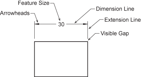
Set-up the Standard Leader in AutoCAD 1. They are uniformly spaced about 1 mm to 2 mm apart. These are thin continuous lines drawn from a dimension figure to the feature to which it refers.
A type B line thin continuous straight going from the instruction to the feature. Iv Construction Lines These are continuous thin lines. Continuous thin wavy Irregular boundary lines short 2H.
Used to indicate the size or location of the geometric feature. C 16A drafter helps in drawing. Thin hidden lines are used as intermittent line types.
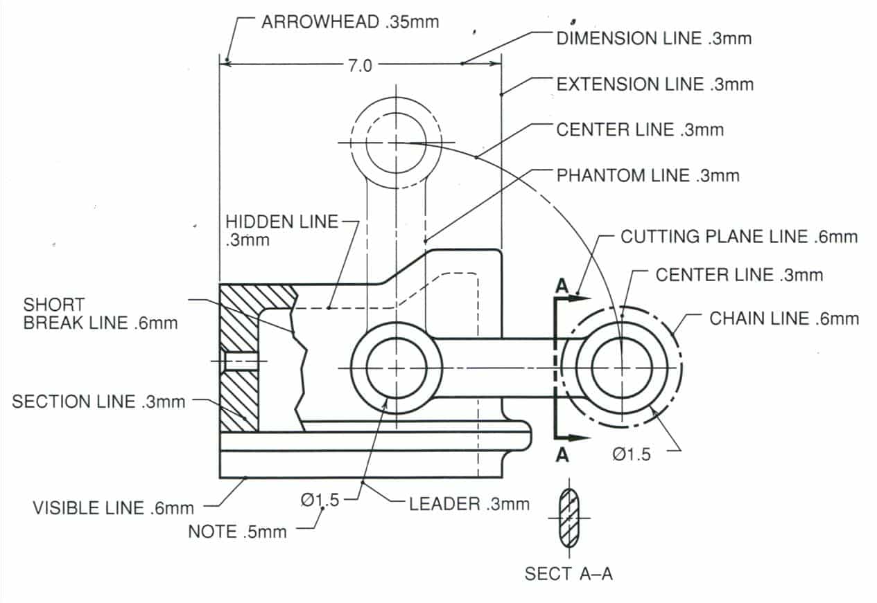
B Long chain thin line. In general application thick lines are 06 mm024. For general engineering drawings the types of lines recommended by the Bureau of Indian Standards shown in table 2 must be used.
A leader line consists of two parts. These lines are used for the main lengths of the object view. Used to indicate the size a geometric feature.
Dimension Marking with Center Lines in Engineering Drawings. V Hatching or Section Lines These are continuous thin lines and generally drawn at an angle of 45 to the main outline of the section. C Smooth free form curve.
What is leader line in engineering drawing. Dots are placed on faces or surfaces. This can be a dot if the line ends within the outline of the part an arrow if the line.
A leader line is a continuous straight line that extends at an angle from a note a dimension or other reference to a feature an arrowhead touches the feature at that end of the leader at the note end a horizontal bar 6 mm long terminates the leader approximately 3 mm away from mid-height of the notes lettering either. Should you be a colorful Lady Then you can certainly take up brighter color tones for the nails if you want delicate factors so certainly your temper will get on nail paints. The B stands for black.
Arrowheads touch object lines. They contain all the information needed to. The H stands for hard B pencils feature softer graphite.
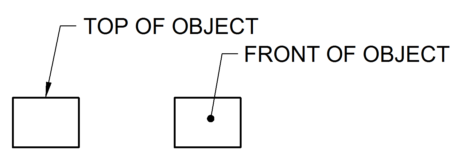
Exercise Complete three orthographic views of the object shown on the next slide. A Continuous thick line. Centre lines Lines of Symmetry Trajectories and Pitch Circles type of lines are long thin chain lines with alternately long and short dashes of proportion ranging from 61 to 41 and evenly spaced.
Leader line is drawn may be 30 or 60 to the bottom of dimensions. The expression of details in terms of numerical. The line of intersection of the horizontal plane HP and Vertical plane VP is represented by XY-Line.
Last Updated on Wed 09 Oct 2019 Engineering Drawing. D Use of common leaders for more than one feature should never be made. B Long chain thin line.
A A leader line is a thin continuous line connecting a note or a dimension figure. The point at which the X- axis or the horizontal line and Y - axis or vertical line intersects to determine the position of any point in the Cartesian plane is called ORIGIN. To create a leader line on the Draw tab under Annotation click.
The wrong statement about leader line is _____________. You can create leader lines with blocks and notes in 2D panel layouts and harness drawings. Set-up Leaders in AutoCAD - Values for Leader Format Tab 2.
Landing settings Automatically include landing. Linetypes And Weight Standards In Technical Drawing. Thin lines are nearly 03 mm012 in most technical drawings.
Add new leader line from start to end HTMLSVG element basically. These are drawn may be vertical or inclined to indicate the height of the dimension figure. B Long chain thin line.
They are drawn for constructing figures. A leader line is a thin line on a design or blueprint that is used to connect a dimension line with a particular area or point on the drawing. First segment angle 60.
This line is used to display the outline and edges of the main drawing done with a pencil softer than HB. Set the divider to a convenient length and mark off seven spaces on AC. Leader linea thin solid line used to indicate the feature with which a dimension note or symbol is associated- Leader lines are generally a straight line drawn at an angle that is neither horizontal nor vertical Leader lines are.
Alternating long-short-long dashed thin line. End of the extension line. Thin line with arrows.
This line is basically used for dimension extension projection leader line etc. The centre lines are extended by a short distance beyond the outline. For general engineering drawings the types of lines recommended by the Bureau of Indian Standards shown in table 2 must be used.
C The leader is drawn vertical or horizontal or curved. Leader or Pointer Lines. An HB pencil is found directly in the center of the scale.
Lets see what types of lines used in engineering drawings. Up to 24 cash back Continuous thin Dimension lines leader lines extension lines Construction lines 2H Hatching lines. Leader Hatching type lines must be drawn thin and continuous.
A leader line is a line referring to some form of feature that could be a dimension an object or an outline. B One end of the leader terminates either in an arrowhead or a dot. C Continuous thin wavy line.
H pencils feature harder graphite. A leader line is a line referring to some form of feature that could be a dimension an object or an outline.

Attaching Datum To Leader Line Or Feature Control Frame Drafting Standards Gd T Tolerance Analysis Eng Tips
Draw The Following Lines Used In Projection I Extension Line Ii Leader Line Iii Construction Line न म नल ख त ल इन क ख च Solutions Ed Question Answer Collection
Dimension Appearance And Technique

About Leader Objects Autocad Lt 2020 Autodesk Knowledge Network

Extension Lines Drafting Joshua Nava Arts
Leader Lines Toolnotes

Engineering Drawing Dimensioning Part 1 Youtube
Technical Drawing Alphabet Of Line Schoolworkhelper
0 comments
Post a Comment